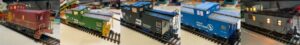
We recently completed the installation of our DCC Decoder LED light board into five HO caboose cars. In the process we had a chance to use several different assembly techniques that I am happy to share. Despite their apparent similarity, including two of identical make and model, they were different enough to warrant some adaptation for each. No two cars were the same, but the general approach is. With a little bit of patience and going slow, you can do this yourself.
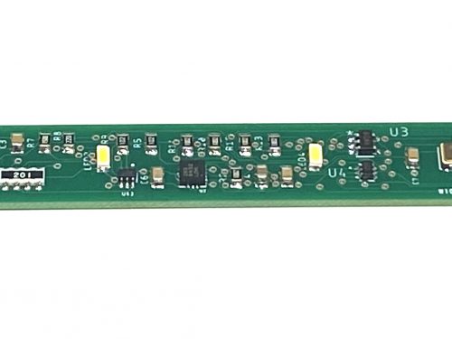
Our Led lightboard for cabooses fits inside both HO and N scale. It has 3 LEDs on the main board plus a set of pads for adding an additional LED connected to the mains. It also has a separate controllable circuit with pads for connecting typically rear red LEDs. In N scale installations we use our prewired 0402 RED LEDs and fit them into a hole in the back wall. We fasten them in place with a little bit of Gallery Glass which dries crystal clear. This combination is fine since N scale is small, it’s both not possible and not necessary to add any kind of fixture.
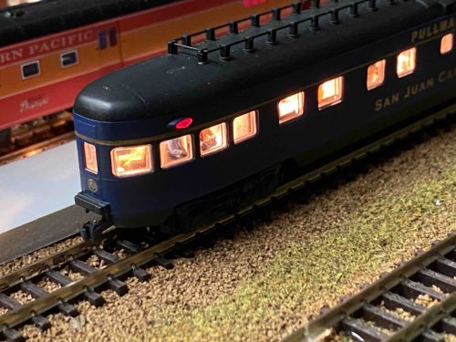
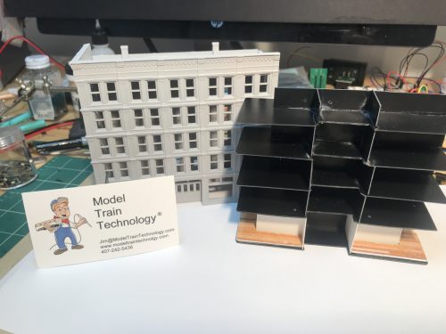
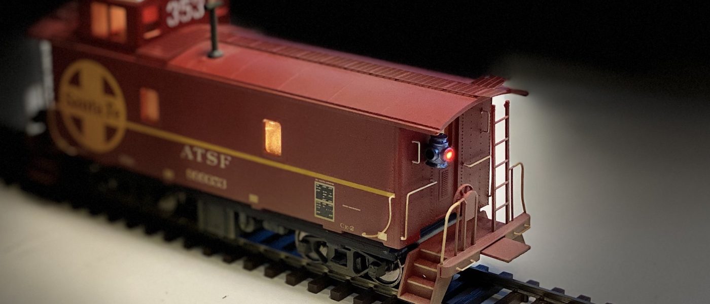
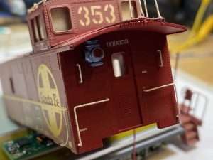
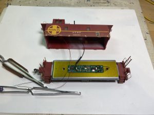
However, when we looked at the installation for these HO cabooses, we decided a lantern to hold the LED would look better. On the Santa Fe car shown above you will notice a lantern attached to the rear wall. We made that with our 3D printer. This was the first car that we decided to tackle and putting the Decoder board in, changing the wheels, adding the Floating Brass® strips went smoothly. We then started looking around for a HO scale lantern and didn’t have much luck. Then we found some picture on Google and decide to see if we could replicate it. Keep reading to see how it turned out.
Here is a list of the Steps:
- Disassemble the car and remove the weight
- Replace wheel sets with one-wheel insulated side.
- Install Model Train Technology Floating Brass® electrical pickups
- Attache double stick tape, Kapton tape to weight
- Attach and connect DCC LED Light Control Board
- Assemble and attach Cupola LED Chip light
- Install 3D printed Lanterns
- Connect wires to LED decoder board
- Test and reassmble
- Take pictures
Removing the body from the chassis reveals the weight that is in every HO caboose. Before you start tugging at the body, remove or disconnect the ladders at either end of the car. Sometimes these are glued in at the base.
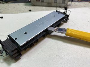
The most difficult, challenging and potentially dangerous step is to remove the flat metal weight from the chassis. After you remove the screws holding it down you are NOT finished – unfortunately. In four of the five cars the weight was also GLUED down. The only way to remove it is to go slowly and carefully slice at the glue from the side. We used a box knife with the blade extended. Push the KNIFE AWAY from you and your fingers!! The knife will get stuck. GO SLOW. Eventually it will come loose.
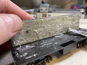
Here you can see the separated weight with the glue. For this car it took about 10 minutes to get it apart. Next we used several cycles of Goof Off (Acetone) to remove the glue to a clean surface. On one of the cars there was a little glue but it was hard. In that case we used 100 grit sandpaper to remove the remainder.
Here you can see the cleaned weight. Don’t use acetone on the plastic, it will melt it and make the plastic gummy. I just used some light sanding to remove the high spots.
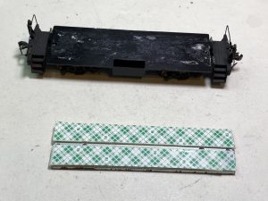
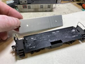
Next we added double stick tape. Notice that there is a center slot/space between the two strips of tape. We’ll run the wheel pick up wires in that grove. Also note that you can see the holes in the metal weight.
KEY FINDING: Don’t waste time trying to drill holes in the weight. We’ll use the screw holes that are already there and just raise the platform with the double stick tape. The tape will hold the weight in place for a lifetime if needed so the screws are redundant.
As an added measure we like to add Kapton tape to the top surface of the weight. Kapton tape is a kind of electrical tape that prevents shorting. You might see it or use it when installing a decoder into and engine. Kapton is thin, non-conducting and easy to work with. Black electrical tape is too bulky and gets gummy. Kapton also holds double stick tape which we will use to attach the LED Light Decoder.
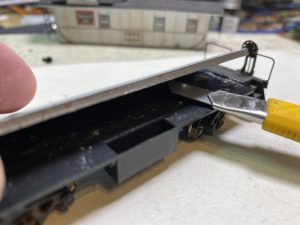
Next we’ll work on the wheel pickup. The first consideration is how to run the wire from the pickups back up into the body of the car. As you can see below, there is a hole that was vacated when we removed the screw holding the weight. You can see that it is to the right of the last wheel and just short of the coupler. This is not the most ideal location, but it will work. Since we now have a slot/space between the chassis and the weight, we can drill a hole almost anywhere to run the wire. I prefer just either side of the truck pinion (where you see the screw) and between the axles. When we attached the Floating Brass®, the wire will move the least as the truck turns. It stays out of the way – which is what we want.
After more than a year hunting for a solution to electrical pickup for cars that don’t have them, we came up with our Floating Brass® idea. This works for all kinds of cars including HO and N passengers cars, which is where we first got the idea. The size and gauge we needed however was not available “anywhere”. We had to have it specially etched for us. In Scotland of all places! There are two sizes. 2mm wide for HO scale and 1mm for N scale.
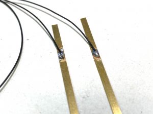
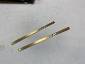
First, tin a little solder onto the brass strip about 1/3 down the length. Use resin core solder since you need the resin to etch/clean the metal to get a good solder bond. Next, we soldered some 36 AWG decoder wire on to the brass. Tin the wire before you solder it to the brass. The length of the wire is about 5-6”.
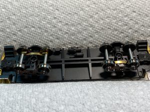
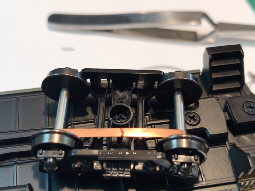
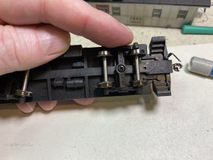
This is the completed view of the wheels with the brass strips. Note that the left side and right-side brass is on a different side of the axle for each truck. The wheels are insulated on one side and you want to put the brass on the NON-insulated side of the pinion screw. Even though we say “floating Brass” the strips will not migrate past the pinion. That way they won’t short the rails.
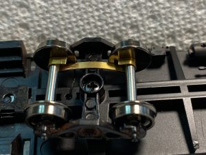
Now that you have the orientation of the brass, the way you install it is with the soldered wire toward the hole (UP). Put the wire through the hole in the body and the slide the flat brass under the axles. Then clip the brass shorter and wrap it around both axles. It will be snug at first. Once in place you can release some of the tension by just pulling gently at the axles away from each other. Notice how much surface area is in contact between the axle and the brass. Quite a lot – far more than the other kind of systems – and in combination with the anti-flicker and capacitors on our LED Decoder Board you get a very reliable lighting system for your caboose. It’s not perfect – as nothing is in model railroading – but it’s the very best available.
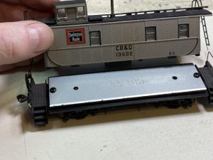
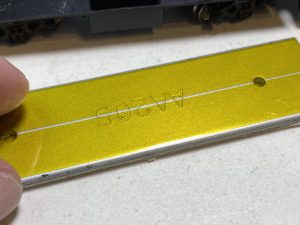
On the top side of the project you can see how the wires from the floating brass® feed through the chassis. Just pull them snug but not too tight and align them with the slot between the double stick tape. Remove the tape and carefully align the weight onto the chassis. Start and one end of the car and lower the tape on to the surface. It will stick very well so alignment is important.
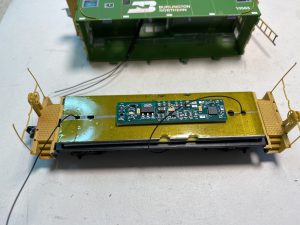
Using double stick tape we attached the LED Decoder Board to the top of the weight.
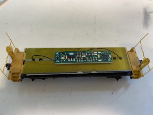
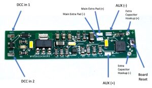
And finally, in this step we soldered the two wire leads to the DCC connection points on the board labeled DCC1 and DCC2. This is a good time to put the car on the track and test the light board.
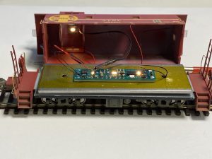
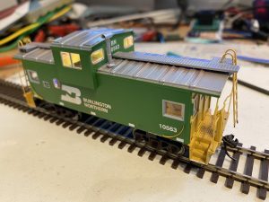
For these installations we added an LED “chip” (2000K) to the ceiling of the cupola. The wires from the chip are soldered onto two pads on the LED Decoder board meant for this purpose. The LED Decoder board has a flicker mode which will make the interior of the caboose look like it had a kerosene lamp. Very nice. (make sure to view the video at the end of this post) Since the ceiling of the cupola is slightly rounded, we use double stick tape to attach it. We also used a small sleeve of shrink tube to keep the wires neat. We did not heat shrink the tube. We just let it loose.
Here is another view of the LED chip and the connection to the LED Decoder board.
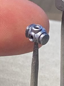
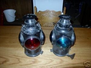
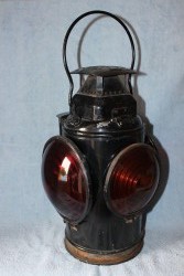
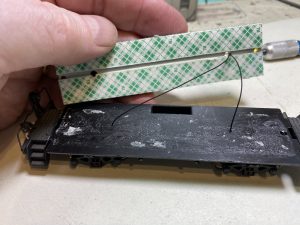
On the left is a picture of the 3D printed lantern. We used Shapr3D on the iPad which is just an amazing piece of software. Very easy to use. Then, on the 3D printer we printed a 5 times larger version to test. Then, using an option on the software for the printer we shrunk the lantern to 1:87 size (HO Scale). You can see that there are holes on each side where the lens should be. One set of holes lets us feed the wires for the LED through. We used 0603 2000K lumen LEDs. (very tiny). For the lens’s we use red and green Gallery Glass. It dries clear – like glass. The Lantern was also airbrush painted with a mix of gray/blue and silver to match the prototype pictures.
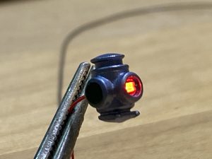
Here you can see the Gallery Glass almost dry. We used a toothpick to drip the liquid into the hole. We did the same for the other sides with Green.
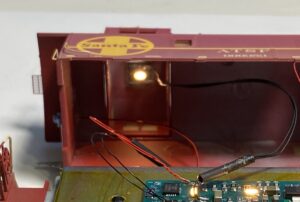
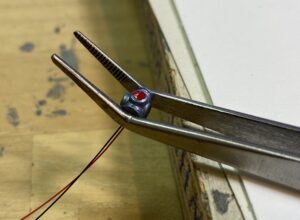
Here the lantern assembly was superglued to the back wall. The wire leads go through a hole in the wall.
Lastly, we connected the front and back lantern wires to the AUX pads on the LED Decoder board. These can be controlled separately and can be set to be solid ON, Blink or Flicker.
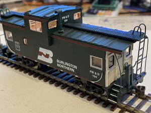
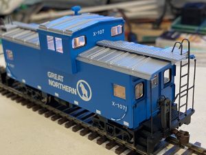
FINISHED INSTALLATIONS:
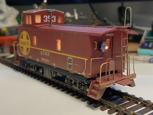
oops ! forgot to attache the ladder before the pictures.
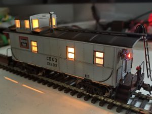
LIVE !!!
Click here to see a live view of the Caboose lighitng
Feel free to write to me if you have any questions.
Jim@ModelTrainMan.com